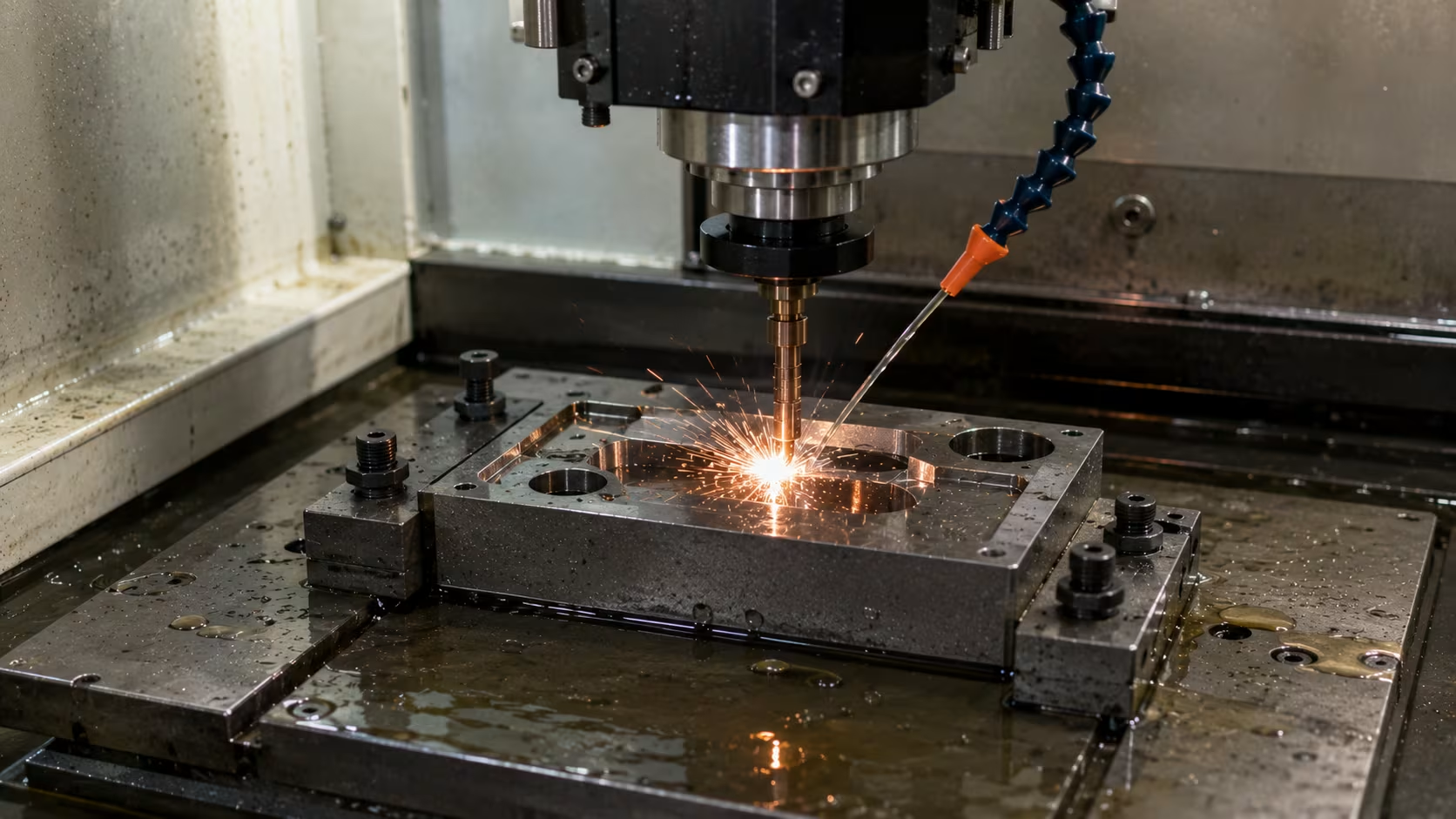
Electric discharge machining (EDM) is one of the most extensively utilized nontraditional machining technologies in today’s production. EDM removes material using controlled electrical discharges or sparks, unlike conventional machining technologies that remove material by direct mechanical cutting. The procedure is notably beneficial for machining hard, electrically conductive materials which are difficult or impossible to manufacture with conventional cutting tools.
It functions by use of spark erosion, a succession of high-frequency electrical discharges between an electrode and a workpiece submerged in a dielectric fluid.
Each spark produces strong local heat which melts and vaporizes small amounts of material. Therefore, very precise and complicated forms may be created without the tool having any direct touch with the workpiece.
I’ve seen a lot of sophisticated production procedures, but EDM remains one of the most interesting machining technologies out there today. Its ability to process hardened steels, carbides and complicated shapes without cutting pressures makes it important in modern workshops. Even with the advent of CNC machining and additive manufacturing, EDM still solves machining problems that many other methods have difficulty with. Generally, to start understanding this fascinating technique, it is best to study the diagram of electric discharge machining.
READ MORE: Heat Treatment Process in Manufacturing: Types and Benefits
Electric Discharge Machining Diagram and Main Components
A typical diagram of electric discharge machining shows the interplay of the electrode tool, workpiece, dielectric fluid, power supply and servo control system.
The key components are:
Power Supplies
The power supply produces the regulated electric pulses that are necessary to make sparks. It controls voltage , current , pulse length and frequency .
Work piece
The workpiece is the conductive substance that is machined. Common materials include hardened steel, titanium alloys, carbide and tool steels.
Electrode Tool
The electrode is employed as the machining tool and is formed to the necessary cavity or profile. It never touches the workpiece directly.
Dielectric liquid
The machining zone is immersed in a dielectric fluid which is an electrical insulator until sufficient voltage is applied to trigger breakdown and spark production.
Servo Control Systems
During cutting the servo system automatically maintains the proper spark gap between the electrode and workpiece.
Spark Gap
The spark gap is the tiny distance between the electrode and the workpiece in which electrical discharges take place. It is important to have the proper distance between the tool and the workpiece in order to machine accurately.
Readers should notice how these components coordinate to provide controlled spark erosion while preserving dimensional precision and process stability when looking at an electric discharge machining schematic.
Working Principle of Electric Discharge Machining
Step 1: Connect the Power
Electrode and workpiece are linked to opposing terminals of the power supply.
Step 2: Spark Gap Formation
A tiny space is kept between the electrode and the workpiece, often 0.01 mm to 0.5 mm.
Step 3: Breakdown of the dielectric
When the voltage increases, the dielectric fluid that sits between the two conducting surfaces starts to break down.
Step 4: Ionization Process
The dielectric fluid becomes ionized, creating a conductive plasma channel.
Step 5: Generate Spark
This creates a spark across the distance. EDM systems usually run at voltages in the range of 50 to 400 volts depending on the machining needs.
Step 6: Local Melting and Vaporization
The temperatures in the plasma channel can surpass above 8,000°C, producing local melting and vaporization of workpiece and electrode material.
Step 7: Removal of Material
The dielectric fluid rapidly cools the molten material and flushes it out, creating small craters on the surface of the workpiece.
Step 8: Machining Cycle Continue
Every second thousands of sparks, slowly building the form and size we want.
This repetitive sparking erosion action is the basis of EDM machining.
Spark Generator and Material Removal Process
The regulated electrical pulses which are used for machining are given by the spark generator.
Generator Relax
Early EDM systems sometimes employed relaxation generators to build up electrical energy and then release it regularly.
Pulse source
Pulse generators increased machining control by better controlling the spark energy.
Modern Transistorized Pulse Generators
Modern EDM machines employ solid state (transistor) pulse generators that allow the user to accurately regulate pulse length, pulse frequency and current.
Significance of Pulse Duration
The pulse length directly affects the crater size, machining speed and surface quality. Short pulses give a better surface polish while lengthy pulses remove more material.
Current Control
By controlling the current well, you may strike a balance between the machining speed and the electrode wear.
Surface roughness
Fine finishing processes employ low energy pulses to produce smoother surfaces.
Reducing tool wear
The pulse parameters are optimized for less electrode wear and higher dimensional accuracy.
Material Removal Rate (MRR)
MRR relies on current, pulse frequency, pulse length, electrode material and dielectric cleansing efficiency.
I think the creation of pulse-controlled machining equipment is one of the most important advances in EDM technology. Modern transistorized generators help producers to obtain outstanding dimensional precision with increased production levels. Today’s EDM machines provide superior surface finishes, decreased electrode wear and increased process stability compared to earlier systems. These developments have extended EDM applicability in many areas of precision production.
Electrode Materials and Dielectric Fluids
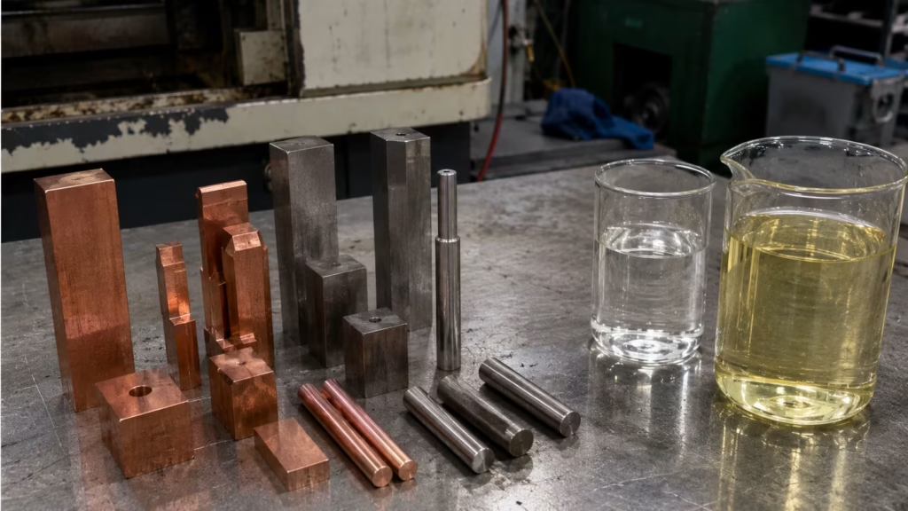
Electrode Materials
Common EDM electrode materials include:
- Copper
- Graphite
- Brass
- Zinc
- Copper tungsten
Good conductivity and precision. Graphite provides rapid machining speeds and less wear in many applications. Tough jobs require toughness and accuracy – copper tungsten delivers both.
Dielectric Fluids
Common dielectric fluids include:
- Kerosene
- Paraffin oil
- Transformer oil
- Filtered dielectric systems
The dielectric fluid cools the machining zone, takes away debris, avoids undesirable arcing and provides steady spark production.
The selection of the electrode has a direct impact on machining speed, tool wear, accuracy, surface polish and the overall efficiency of production.
Types of Electric Discharge Machining
Wire EDM (WEDM)
Wire EDM cuts complicated curves and sophisticated profiles using a continually moving wire electrode. It is commonly utilized in tool rooms and precision component manufacture.
Sinker EDM (SEDM)
Sinker EDM employs a shaped electrode to create cavities, molds, and die impressions. It is commonly used in die and mold manufacturing.
Hole Drilling EDM
Hole drilling EDM creates deep, precise holes in hard materials and is frequently used in aerospace and turbine component production.
Overcut, Accuracy and Design Considerations
Overcut in EDM: Overcut refers to the difference between electrode dimensions and the final machined cavity caused by spark gap clearance.
Machining Accuracy: Modern EDM machines can achieve extremely high precision with tight dimensional control.
Surface Finish: Surface finish depends on pulse parameters, electrode material, and machining conditions.
Tool Wear: Electrode wear must be considered during tool design and process planning.
Tolerance Capability: EDM can achieve tolerances within a few microns in specialized applications.
Design Limitations: Only electrically conductive materials can be machined using EDM.
Manufacturing Considerations: Proper flushing, electrode design, and machine parameter selection are essential for consistent results.
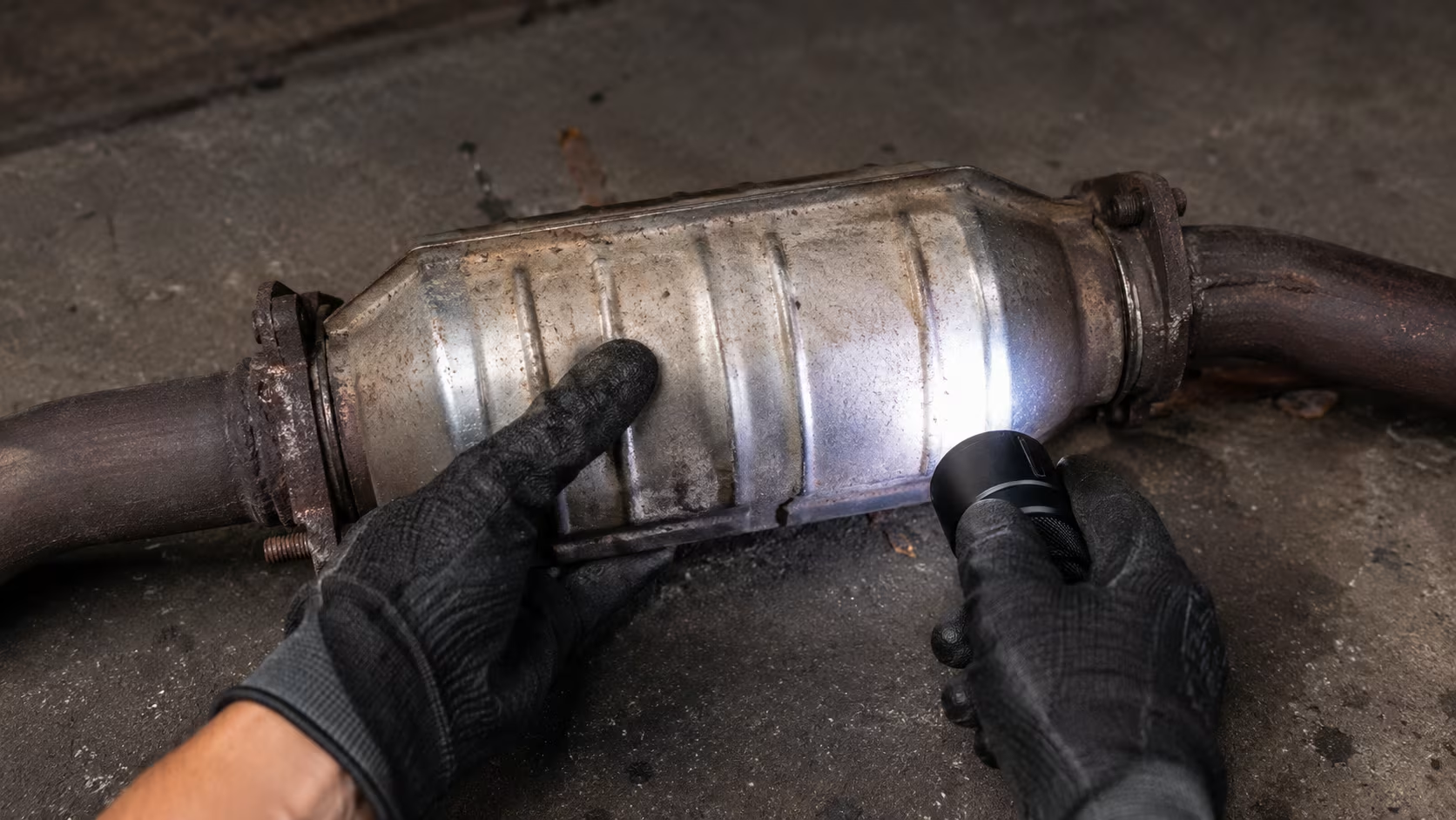
Applications of Electric Discharge Machining
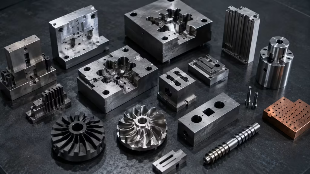
EDM plays a critical role in numerous manufacturing sectors.
Common Industrial Applications
- Die and mold manufacturing
- Aerospace components
- Forging dies
- Extrusion dies
- Tool and die industry
- Carbide machining
- Hardened steel machining
- Precision engineering
- Medical components
- Automotive manufacturing
Industries rely on EDM whenever conventional machining becomes difficult due to material hardness or geometric complexity.
Advantages of Electric Discharge Machining
Major advantages include:
- Machines extremely hard conductive materials
- No direct tool-workpiece contact
- Produces complex geometries
- High dimensional accuracy
- Excellent surface finish capability
- Minimal cutting forces
- Suitable for delicate components
- Effective for deep cavities and intricate shapes
Disadvantages of Electric Discharge Machining
Key limitations include:
- Limited to electrically conductive materials
- Slower than some conventional machining methods
- Electrode wear occurs during machining
- Higher equipment costs
- Dielectric fluid maintenance required
- Heat-affected zones may form under certain conditions
Conclusion
Electric Discharge Machining is a very sophisticated manufacturing method in which material is removed by use of controlled electrical discharges instead of normal cutting action. To visualize the link between power supply, electrode, dielectric fluid, servo system and workpiece, the electric discharge machining diagram is helpful to engineers and students. EDM’s capacity to generate very accurate features in tough and difficult-to-machine materials, making it a crucial technology for the aerospace, automotive, medical, tooling and precision engineering sectors.
From a production standpoint, EDM is still one of the most useful machining technologies available. It is relevant in today’s manufacturing contexts because of its capacity to produce complicated forms with precise precision. With industries requiring finer tolerances and more complex components, EDM will only become more important.
The combination of accuracy, flexibility and dependability means that EDM will remain a cornerstone of sophisticated production for years to come.