In current automotive documentation, manual transmission explained material often reflects a consistent structure across manufacturers and training archives. The phrase manual transmission explained appears in both service literature and workshop references, where mechanical relationships are recorded rather than interpreted.
Within these records, how manual transmission works in a car step by step is typically outlined alongside gear engagement patterns and clutch interaction. The same systems appear across different motorcycles and passenger vehicles, including discussions that reference kinds of motor bikes in broader drivetrain comparisons.
As a result, manual transmission explained content remains closely tied to observed mechanical layouts rather than changing presentation formats.
Manual Transmission Explained with Diagram
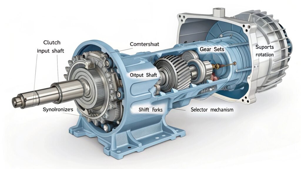
In technical references, manual transmission explained sections usually appear alongside simplified diagrams that map the relationship between the engine, clutch, input shaft, gear sets, and output shaft. The diagrams illustrate the movement of torque through aligned shafts and gear changes determine the direction and speed of rotation.
The diagrams have been made with respect to cars where only the casing and gear pattern differ from one another. Diagrams of gearboxes have always emphasized constant mesh engagement, the presence of synchronizers, and the positioning of selector forks. The purpose of this diagram is not to explain performance, but the mechanics of motion.
Parts of Manual Transmission and Their Functions
Within service documentation, manual transmission explained content often organizes components based on their role in torque transfer and gear selection. The setup shows a system whereby every component acts in coordination rather than working individually. Mechanism depends on proper alignment, lubrication, and balancing of the loads that act on rotating components.
Core Mechanical Components
- Clutch Assembly – connects and disconnects engine torque from the gearbox input shaft
- Input Shaft – receives rotational force directly from the engine
- Output Shaft – transfers adjusted torque to the driveshaft
- Countershaft (Layshaft) – maintains constant gear engagement with input shaft gears
Gear Engagement System
- Gear Sets – provide different ratios that alter speed and torque
- Synchronizer Rings – align gear speeds before engagement
- Dog Clutches – lock selected gears to the shaft
Control and Support Elements
- Shift Forks – move synchronizers across gear sets
- Gear Selector Mechanism – translates driver input into gear movement
- Transmission Case – houses and supports internal components
How Manual Transmission Works in a Car Step by Step
In workshop literature, manual transmission explained descriptions of operation follow a sequence that reflects interaction between clutch movement, shaft rotation, and gear engagement. The process appears consistent across most mechanical layouts, with minor variation in synchronizer design and linkage response.
| Step | Mechanical Action | System Behavior |
| 1 | Clutch pedal depressed | Engine disconnects from gearbox input shaft |
| 2 | Gear lever moved | Selector forks shift synchronizer position |
| 3 | Synchronizer engages | Gear speed aligns with shaft speed |
| 4 | Gear locks in place | Dog clutch connects gear to output shaft |
| 5 | Clutch released | Torque flows from engine to transmission |
| 6 | Vehicle moves | Output shaft transfers motion to drivetrain |
Manual Gearbox Components and Working Principle
The gearbox definition in engineering summary articles related to manual transmission indicates the gearbox as an apparatus that regulates the torque by means of preset gear ratios, keeping gear engagement constant. The functioning theory of the apparatus can be viewed as a rotational process in parallel shafts where variations in speed are achieved through locking gears.
- Power enters through the input shaft and moves to the countershaft
- Gears remain in constant mesh, reducing direct engagement wear
- Synchronizers regulate speed differences before gear locking
- Output shaft rotation reflects selected gear ratio
- Torque variation appears as a function of gear size and engagement position
Types of Manual Transmission in Automobiles
The classification of systems in manual transmission explained material reflects historical development and changes in gear engagement methods. Variations appear in how gears connect and how speed alignment is managed.
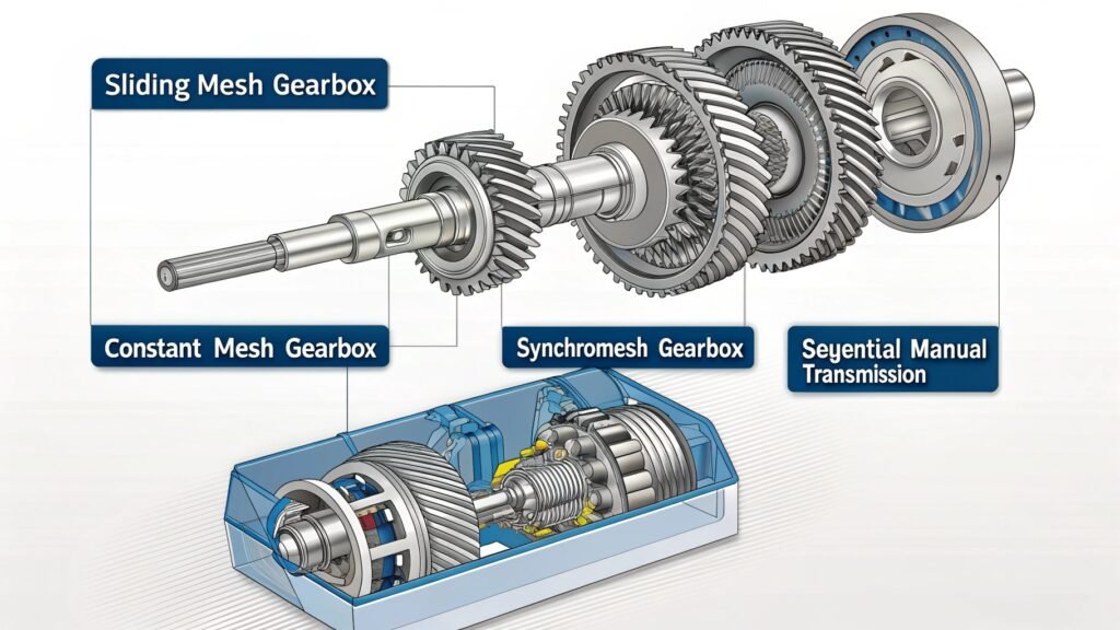
Sliding Mesh Gearbox
Gears slide directly into engagement. Contact occurs without synchronization, which reflects earlier mechanical layouts.
Constant Mesh Gearbox
All gears remain engaged. Selection occurs through dog clutches rather than direct gear movement.
Synchromesh Gearbox
Synchronizers align rotational speed before engagement. This arrangement appears in most modern vehicles.
Sequential Manual Transmission
Gear selection follows a fixed order. The system appears in motorcycles and performance-focused applications.
Synchromesh Gearbox Working and Advantages
In most present systems where manual transmissions are used, the discussion on synchromesh refers to a process whereby the speeds of gears are matched through frictional surfaces before engagement takes place. In this case, the synchromesh ring helps in matching the speeds through proper control of contacting parts.
- Synchronizer cones create friction to match gear speeds
- Engagement occurs after rotational alignment
- Reduced gear noise appears during shifting
- Wear distribution remains more even across components
- Driver input translates into smoother mechanical response
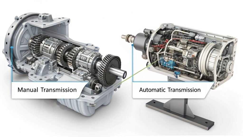
Manual Transmission vs Automatic Transmission Comparison
In comparative analysis, manual transmission explained sections often contrast mechanical control with automated hydraulic or electronic systems. The difference appears in how gear selection occurs and how torque transfer is managed under varying load conditions.
| Feature | Manual Transmission | Automatic Transmission |
| Gear Selection | Driver controlled | System controlled |
| Clutch Operation | Mechanical pedal | Hydraulic or electronic |
| Torque Transfer | Direct mechanical link | Fluid coupling or torque converter |
| Maintenance Pattern | Component-specific wear | System-level servicing |
| Fuel Behavior | Reflects driver input | Adjusted by control unit |
Common Manual Transmission Problems and Solutions
Operational records show that manual transmission explained sections often include recurring fault patterns linked to wear, lubrication, and alignment. These conditions appear gradually and reflect mechanical stress over time rather than sudden system failure.
| Problem | Possible Causes |
| Gear slipping | Worn synchronizers or dog clutches |
| Grinding noise | Incomplete synchronization or clutch wear |
| Difficulty shifting | Linkage misalignment or low fluid levels |
| Clutch drag | Improper disengagement or pressure plate wear |
| Transmission noise | Bearing wear or insufficient lubrication |
Signs of Manual Transmission Failure in Cars
In diagnostic summaries, manual transmission explained material identifies patterns that indicate system decline. These signs appear in sound, resistance, and irregular movement during operation.
- Delayed gear engagement during shifting
- Unusual noise during acceleration or deceleration
- Increased resistance in gear lever movement
- Fluid leakage around transmission housing
- Inconsistent clutch response during operation
How Clutch Works in Manual Transmission System
In mechanical descriptions, manual transmission explained sections treat the clutch as an interface between engine output and gearbox input. The clutch operates through friction plates that engage and disengage rotational motion. When the pedal is pressed, the pressure plate releases the clutch disc, interrupting torque flow.
When released, the disc reconnects with the flywheel, restoring motion transfer. The system behaves as a controlled interruption mechanism, allowing gear selection without continuous load on the transmission.
Gear Shifting Process in Manual Transmission Explained
In the drivetrain manuals, manual transmissions that cover the gear selection aspects usually conform to the behavior of linkage systems as opposed to driver instructions. As such, the gear selecting procedure in the manual transmission covered by these documents reveals the movement of the selector forks in the shift rails engaging the synchronizers, which facilitate the alignment of the speeds between the gears.
The separation of the clutch ensures that the torque produced by the engine is disconnected from the input shaft, ensuring proper engagement of the gears.
Advantages and Disadvantages of Manual Transmission
While comparing drivetrains, the discussion about manual transmission benefits and drawbacks is usually combined with the analysis of performance differences that occur due to various load and traffic conditions.
Strengths and weaknesses associated with manual transmissions relate to mechanical simplicity, gear shifting performed by the driver, and clutch coordination.
These features remain consistent in markets characterized by diverse fuel performance, maintenance cycles, and transmission wear rates regardless of design modifications.
Advantages of Manual Transmission
- Mechanical layout remains simpler than automatic transmission systems
- Gear selection remains directly controlled through driver input
- Transmission losses appear lower in steady-state driving conditions
- Manufacturing structure reflects fewer hydraulic and electronic components
- Maintenance cycles remain predictable in low-load operating environments
Disadvantages of Manual Transmission
- Clutch wear appears higher in dense traffic conditions
- Gear shifting depends on operator consistency and timing
- Torque interruption occurs during gear transitions
- Urban driving behavior reflects increased physical input
- Learning curve remains present for new drivers
Conclusion
In technical records, manual transmission explained content remains tied to mechanical interaction between clutch systems, gear ratios, and gearbox components. The same manual transmission explained structure appears across vehicle platforms where manual gearbox behavior reflects stable design principles.
Variations occur in transmission systems and gear shifting patterns under different operating loads. These observations align with broader automotive transmission comparisons, where manual transmission and automatic transmission continue to coexist within changing vehicle configurations.