Modern trucks and buses require an air brake system for safe operation due to heavy loading and extensive distances covered. As indicated by the Federal Motor Carrier Safety Administration, violation of regulations concerning brakes is one of the most common violations when checking commercial vehicles on the roads.
An efficient air brake system makes use of air pressure, brake chambers, and brake valves to generate consistent stopping power, even under high-pressure scenarios.
Unlike regular hydraulic brakes employed in ordinary cars, truck brakes operate on the principle of air brakes, where compressed air provides more consistent braking force.
Knowledge of how the air brake system works will help drivers, mechanics, and students of mechanical engineering detect brake problems like pressure loss, brake chamber damage, and other issues associated with the braking mechanism.
How Do Air Brakes Work In Trucks
The air brake system in trucks uses compressed air instead of brake fluid. The braking mechanism begins at the air compressor. The compressor builds brake pressure and stores it inside air reservoirs. The stored air moves through brake valves and brake chambers during braking operations.
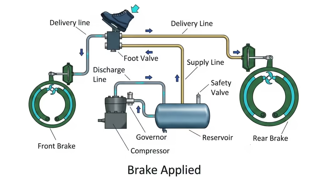
The air brake system operates through a sequence of pressure release and mechanical force transfer. The driver presses the brake pedal. The brake valves release compressed air into the brake chamber. The chamber pushes a slack adjuster. The adjuster rotates the brake cam. The brake shoes move against the brake drum. Friction slows the heavy vehicle brakes during motion.
Main Components In Truck Brake Operation
| Component | Function |
| Air Compressor | Produces compressed air |
| Air Reservoir | Stores brake pressure |
| Brake Valves | Controls air movement |
| Brake Chamber | Converts air pressure into force |
| Slack Adjuster | Transfers movement to brake cam |
| Brake Drum | Creates friction for stopping |
| Parking Brakes | Holds vehicle during stationary condition |
Dual brake systems separate front and rear braking circuits. The arrangement reduces total brake loss during pressure failure conditions.
Air Brake System Troubleshooting Guide
The air brake system shows pressure loss, delayed braking, or unusual air leakage when faults appear inside the pneumatic system. Most brake troubleshooting procedures begin with air pressure inspection. Low brake pressure usually reflects compressor wear, air leakage, or damaged brake valves.
Common Brake System Problems
- Low brake pressure
- Slow pressure build-up
- Brake chamber leakage
- Uneven braking force
- Faulty brake valves
- Worn slack adjusters
- Moisture inside air reservoirs
- Compressor overheating
Frozen valves restrict compressed air movement inside commercial vehicle brakes.
Symptoms And Possible Causes
| Symptom | Possible Cause |
| Constant air leakage | Damaged hose or fitting |
| Weak braking force | Low brake pressure |
| Delayed brake response | Faulty brake valves |
| Vehicle pulling sideways | Uneven brake adjustment |
| Warning light activation | Pressure imbalance |
| Excessive compressor cycling | Reservoir leakage |
The air brake system requires periodic brake inspection because worn mechanical braking parts gradually affect stopping distance and brake pressure balance.
Air Brake System Inspection Procedure
The air brake system inspection procedure follows a sequence that checks brake pressure, mechanical movement, and leakage conditions. Commercial transport operators perform inspections before vehicle movement. Brake inspection procedures appear in most transport safety regulations.
Standard Inspection Areas
- Air compressor condition
- Air reservoir pressure level
- Brake chamber movement
- Brake hose leakage
- Brake valve response
- Parking brake engagement
- Emergency brake activation
- Brake drum wear condition
Excessive pressure reduction reflects leakage inside the pneumatic brakes network.
Typical Pressure Loss Limits
| Vehicle Type | Maximum Pressure Loss |
| Single Commercial Vehicle | 3 pounds per square inch per minute |
| Combination Vehicle | 4 pounds per square inch per minute |
Excessive pushrod travel reflects brake adjustment issues inside heavy vehicle brakes.
Air Brake System Pressure Requirements
The air brake system depends on stable brake pressure for proper operation. Most truck brakes operate between 100 and 125 pounds per square inch. Air compressors maintain this range during vehicle movement.
Recommended Pressure Ranges
| System Condition | Pressure Range |
| Normal Operating Pressure | 100 to 125 pounds per square inch |
| Low Pressure Warning | Below 60 pounds per square inch |
| Compressor Cut-Out Pressure | Around 125 pounds per square inch |
| Emergency Brake Activation | Around 20 to 45 pounds per square inch |
The warning systems activate when brake pressure falls below safe operating levels.
Air Brake System Working Principle
The air brake system operates through compressed air stored inside air reservoirs. An air compressor produces compressed air during engine operation. The compressor transfers air into storage tanks through brake valves and pressure regulators.
The braking mechanism follows a sequential process:
- Air compressor builds brake pressure
- Air reservoir stores compressed air
- Brake pedal releases controlled air pressure
- Brake chamber converts pressure into force
- Brake shoes contact the brake drum
- Vehicle speed reduces gradually
Pneumatic brakes remain suitable for heavy vehicle brakes because compressed air replenishes continuously during engine movement.
Compressed Air Brake System Explained
The air brake system uses compressed air instead of brake fluid. Commercial vehicle brakes rely on pneumatic pressure because heavy transport vehicles require greater braking force. The system behaves differently from hydraulic brake systems during long-distance operation.
| Air Brake Component | Operational Role |
| Air Compressor | Produces compressed air |
| Air Reservoir | Stores brake pressure |
| Brake Valve | Controls air movement |
| Brake Chamber | Converts pressure into force |
| Slack Adjuster | Transfers mechanical movement |
| Brake Drum | Creates wheel stopping friction |
These sections operate through spring brake assemblies. Spring brakes remain active when air pressure drops below the required level.
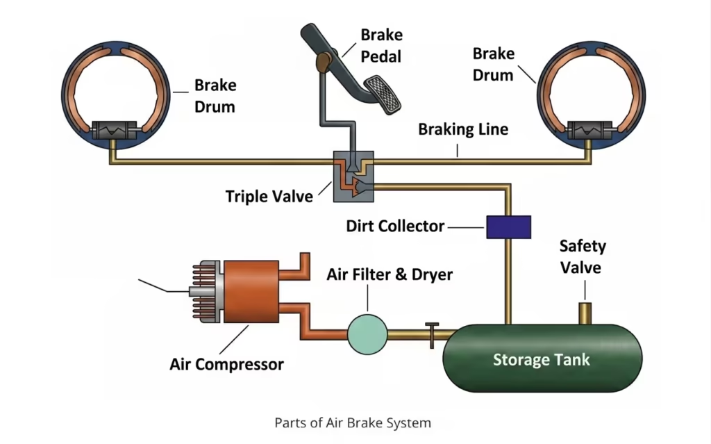
Parts Of Air Brake System And Functions
The air brake system contains multiple mechanical braking parts connected through pneumatic lines. Each brake component performs a separate operational function inside the braking system.
Main Parts Of The Air Brake System
Air Compressor
The brake system receives compressed air from the air compressor. The compressor operates through engine power. Brake pressure builds gradually inside the storage tanks.
Air Reservoir
The air reservoir stores compressed air for future braking cycles. The brake system uses separate reservoirs in dual brake system layouts. Pressure remains available even when repeated braking occurs.
Brake Chamber
The brake chamber converts pneumatic pressure into linear force. The brake system transfers this force toward the slack adjuster and brake shoes.
Brake Valve
Brake valves regulate compressed air movement. The brake system uses relay valves, foot valves, and safety valves during operation.
Brake Drum And Brake Shoes
Brake shoes contact the brake drum during braking movement. Friction develops between both surfaces. The brake system reduces wheel rotation through this mechanical braking process.
Components Of Air Brake System
The air brake system contains pneumatic, mechanical, and safety-related components. Heavy vehicle brakes require coordinated movement between these sections during operation.
Core Components
- Air compressor
- Governor valve
- Air reservoir
- Brake chamber
- Brake lines
- Relay valve
- Slack adjuster
- Brake drum
- Brake shoes
- Parking brake assembly.
What Is Air Brake System In Vehicles
The air brake system refers to a braking mechanism that uses compressed air for vehicle deceleration. Heavy trucks, buses, trailers, and industrial vehicles commonly use this braking technology because hydraulic brake systems behave differently under high vehicle loads.
Vehicle braking systems using compressed air generally appear in:
- Semi-trucks
- Public transport buses
- Construction vehicles
- Freight trailers
- Mining vehicles
The brake system remains suitable for commercial vehicle brakes because pneumatic pressure replenishes continuously during engine operation.
Air Brake System Safety Features
The air brake system includes several safety mechanisms designed for pressure stability and emergency braking operation. These systems reduce uncontrolled brake failure during transport movement.
Common Safety Features
| Safety Feature | Operational Function |
| Low Pressure Warning | Indicates pressure reduction |
| Dual Brake System | Separates front and rear braking circuits |
| Spring Brake | Activates during air pressure loss |
| Safety Valve | Releases excessive pressure |
| Pressure Gauge | Displays current brake pressure |
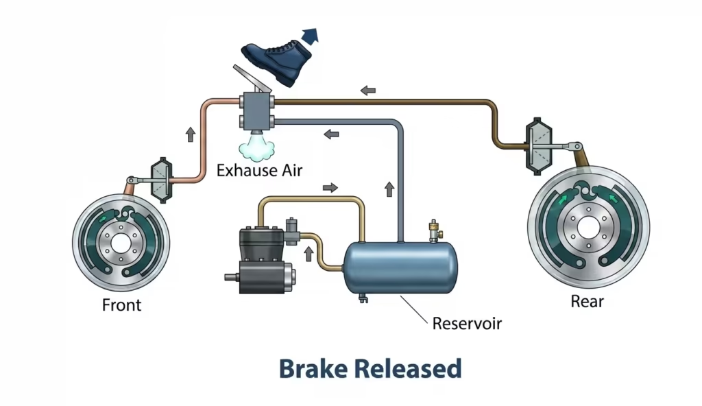
The brake system also contains emergency brakes connected through spring-loaded assemblies. Spring brakes remain engaged when compressed air becomes unavailable. This design prevents uncontrolled vehicle movement during air leakage conditions.
Air Brake System Advantages And Disadvantages
The air brake system behaves differently from hydraulic braking systems during commercial transport operation. Pneumatic brakes provide operational advantages under heavy load conditions. Some mechanical limitations also remain present.
Advantages Of Air Brake System
| Advantage | Observation |
| Continuous Air Supply | Compressor restores pressure regularly |
| Suitable For Heavy Vehicles | Higher braking force remains available |
| Lower Risk Of Complete Brake Failure | Minor leakage does not stop total operation |
| Multiple Safety Systems | Emergency brakes remain connected |
| Long-Distance Operation | Brake pressure remains stable |
Disadvantages Of Air Brake System
| Disadvantage | Observation |
| Larger System Size | More components remain connected |
| Higher Maintenance Requirement | Brake valves and chambers require inspection |
| Moisture Accumulation | Water may collect inside air lines |
| Slower Response Time | Air movement requires short delay |
| Noise Generation | Pneumatic release produces sound |
Air Brake System Inspection Procedure
The air brake system inspection procedure begins with a visual examination of the brake components. Mechanics inspect the air compressor, brake chamber, brake valves, and air reservoir for visible leakage or physical damage. Brake hoses remain checked for cracks, cuts, or loose fittings. Commercial vehicle brakes operate under constant vibration conditions. Hose wear appears frequently near connection points.
Common Inspection Areas
| Brake Component | Inspection Focus |
| Air Compressor | Pressure generation rate |
| Brake Chamber | Air leakage and pushrod travel |
| Brake Valves | Valve response and sealing |
| Air Reservoir | Moisture buildup |
| Brake Hoses | Cracks and loose fittings |
| Pressure Gauge | Stable pressure readings |
Air Brake System Safety Features
The air brake system contains several transport safety controls designed for heavy commercial vehicles. Dual brake systems remain one of the most common safety features. Separate air circuits operate independently for front and rear truck brakes. Partial braking capacity remains available if one circuit loses pressure.
Major Safety Features In Air Brake Systems
- Dual brake system
- Emergency brake mechanism
- Low-pressure warning devices
- Air pressure gauges
- Parking brake systems
- Air reservoir storage system
Air Brake System Pressure Requirements
The air brake system operates within a controlled pressure range that supports stable braking performance. Most commercial vehicle brakes function between 100 and 125 pounds per square inch during standard operating conditions. The air compressor maintains this pressure range automatically through governor-controlled operation.
Standard Pressure Conditions
| Pressure Condition | Approximate Range |
| Governor Cut-In Pressure | 100 PSI |
| Governor Cut-Out Pressure | 125 PSI |
| Low Pressure Warning | Below 60 PSI |
| Emergency Brake Activation | Around 20 to 45 PSI |
Air Brake System Troubleshooting Guide
The air brake system troubleshooting process focuses on identifying pressure loss, delayed braking response, and abnormal brake noise. Air leakage remains one of the most common faults in compressed air brakes. Leakage frequently appears near brake hoses, fittings, or damaged brake chambers.
Common Air Brake Problems
| Problem | Possible Cause |
| Low Brake Pressure | Air leakage or compressor failure |
| Slow Brake Response | Valve blockage |
| Continuous Air Leakage | Damaged brake hose |
| Brake Dragging | Brake chamber malfunction |
| Moisture In System | Faulty air dryer |
| Uneven Braking | Brake adjustment problem |
Conclusion
The air brake system remains a standard braking technology in trucks, buses, and commercial transport vehicles. The braking mechanism depends on compressed air pressure, brake valves, air reservoirs, and brake chambers for stable operation.
Regular brake inspection procedures help identify leakage, pressure imbalance, and brake component wear. Safety controls such as emergency brakes, dual brake systems, and pressure warning devices remain central to transport safety in heavy vehicle brakes.